Clip Angle Settings
- General Overview
- Tips and Tricks
- Related Tools
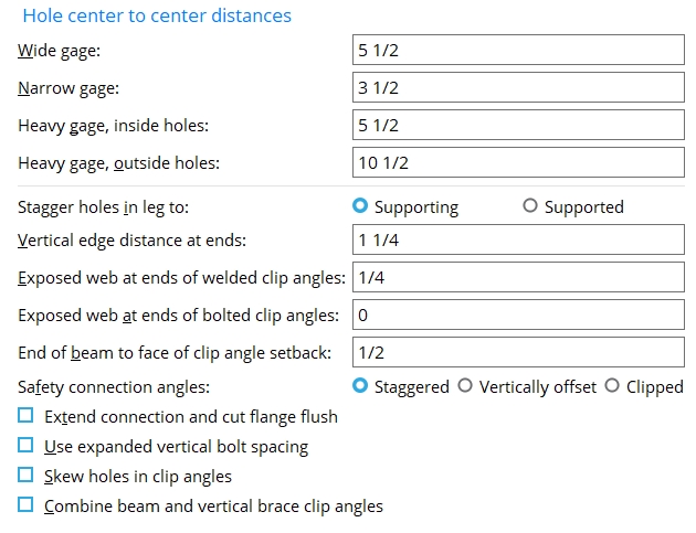
Hole center to center distances
Wide gage: The center-to-center distance from the column of holes on the one clip angle to the column of holes on the other clip angle.
|
g = gage. Connection design creates wide gage clip angles when ' Wide ' (beam) or ' Wide ' (joist) has been specified as the " Gage " in " |
Effect on connection design: The double clip angle connection gage entered here applies to the connection design of wide gage double clip angles. Such clip angles are designed per the setup configurations Wide Gage OSL All-Bolted Clip Angles and Wide Gage OSL Bolted/Welded Clip Angles . This center-to-center gage also affects the leg gages that are listed on the " Clip Angle Piecemarks " tables found on the wide gage clip angle configuration setup screens.
Narrow gage: The center-to-center distance from the column of holes on the one clip angle to the column of holes on the other clip angle.
|
|
g = gage. Connection design creates narrow gage clip angles when ' Narrow ' (beam) or ' Narrow ' (joist) has been specified as the " Gage " in " |
Effect on connection design: The double clip angle connection gage entered here applies to the connection design of narrow gage double clip angles. Such clip angles are designed per the setup configurations Narrow Gage OSL All-Bolted Clip Angles and Narrow Gage OSL Bolted/Welded Clip Angles . This center-to-center gage also affects the leg gages that are listed on the " Clip Angle Piecemarks " tables found on the narrow gage clip angle configuration setup screens.
Heavy gage, inside holes: The center-to-center distance from the inside column of holes on one clip angle to the inside column of holes on the other clip angle.
Effect on connection design: The double clip angle connection gage entered here defines the distance between the inside bolt columns on heavy gage double clip angles. Heavy gage clip angles typically have two columns of bolts. Heavy gage clip angles are designed when 'Heavy' (beam) or 'Heavy' (joist) is the specified " Gage ." This center-to-center gage also affects the leg gages listed on the " Clip Angle Piecemarks " tables for Heavy Gage OSL All-Bolted Clip Angles and Heavy Gage OSL Bolted/Welded Clip Angles clip angles.
Heavy gage, outside holes: The center-to-center distance from the outside column of holes on the one clip angle to the outside column of holes on the other clip angle.
Tip: If your Job doesn't use clip angles with two columns of holes, setting this distance to be the same as the " Heavy gage, inside holes " gives you a third single gage option.
Other clip angle settings
Stagger holes in leg to: Supporting or Supported . The selection made here applies in default situations. You can override the choice you make here by using " Stagger " (beams) or " Stagger " (joists) for individual connections.
' Supporting ' places the top hole in the angle leg to the supporting member at the normal edge distance plus half the vertical spacing (Vertical edge distance at ends + [ Bolt spacing / 2]).
' Supported ' places the top hole in the angle leg to the joist's knife plate at the normal edge distance plus half the vertical spacing ( Vertical edge distance at ends + [ Bolt spacing / 2]).
Project Settings: " Bolt spacing " is set per bolt diameter at Home > Project Settings > Fabricator > Detailing > Connection Erectability Settings . "Vertical edge distance at ends" is set at Home > Project Settings > Fabricator > Standard Fabricator Connections > Clip Angle Settings .
Vertical edge distance at ends: The distance parallel with the length of the clip angle from the outside edge of the clip angle to the center of the nearest hole. This applies to vertical brace gusset clips, horizontal brace gusset clips, flushed framed joist clip angles, and clip angles on beams.
|
v = vertical edge distance |
For clip angles on beams: Connection design uses the minimum edge distance from the Table Reference specified below or the value entered to Vertical edge distance at ends, whichever is greater.
For horizontal and vertical brace gusset clips: Connection design uses the maximum of the value from the table specified below or the value entered to Vertical edge distance at ends when it designs clip angles for attaching the gusset of a horizontal brace or vertical brace to a supporting member. Two setup options that instruct connection design to override this general rule are: Allow reduced edge distance for 7/8" and 1" bolts (horizontal braces) and Allow reduced edge distance for 7/8" and 1" bolts (vertical braces).
Method Table Reference ASD 16 Table J3.4 or Table J3.4M ASD 15 ASD 14 ASD 13 ASD 9 Table J3.5 LRFD 16 Table J3.4 or Table J3.4M LRFD 15 LRFD 14 LRFD 13 LRFD 3 CISC 12 Table 5 CISC 11 Table 6 CISC 10
CISC 9 CISC 8 AS 4100 - 1998 Table 9.6.2 CHINA GB50017 - 2003 Table 8.3.4 INDIA IS 800:2007 Table 8.3.4
Exposed web at ends of welded clip angles: The distance from the top (or bottom) of the clip angle to the cope on the supported beam.
|
xw = exposed web. This distance must be sufficient to allow the clip angle to be welded to the beam. |
Effect on connection design: The exposed web must be at least 1/16 inch larger than the weld size that connection design has determined is required for the applied " Shear load ." If the exposed web is insufficient, the following connection failure message is generated: " Web projection above clip is too small for weld ."
Exposed web at ends of bolted clip angles: The vertical distance from the top (or bottom) of the clip angle to the cope on the supported beam.
|
xw = exposed web. Since no weld is required on a bolted clip angle, the exposed web can be set to 0 (zero) if desired. |
End of beam to face of clip angle setback: The distance between the end of the supported beam or joist and the face of the clip angle's outstanding leg.
|
s = setback for the end of the beam to the face of the clip angle. |
Tip: On the Beam Edit window, under the "
Setbacks " leaf, you can use the " Connection setback " entry field to adjust this setback for an individual clip angle connection.
Safety connection angles: Staggered or Vertically offset or Clipped . This option is for clip angles on two beams framing to opposite sides of a supporting web (beam or column) so that the clip angle connections on both supported members share bolts. The option you choose here is applied when ' Safety ' (beams) or ' Safety ' (joists) or has been selected for system-designed clip angle connections. ' Safety ' needs to be set for only one of the opposing members, but both members must have clip angle connections. This will not work for bolted-bolted clip angles with staggered bolts.
|
|
|
' Staggered ' causes one of the double clip angles to move down one bolt space so that one angle is staggered with respect to the other angle on the same beam (or joist). One bolt (either the upper or lower bolt) on each of the double clip angles is not shared by the connecting clip angle on the opposing beam (or joist).
' Vertically offset ' moves both angles down one bolt space so that both angles are vertically offset with respect to the clip angles on the opposing beam (or joist). This results in two "free" bolts at the top of the double clip angles on the one beam and two "free" bolts at the bottom of the clip angles on the opposing beam (or joist).
' Clipped ' produces staggered clip angles, with one clip angle shorter than the other so that each of the longer clip angles has one "free" bolt that is not shared by the clip angle on the opposing beam (or joist). To accomplish this, the NS angle on the left-end connection is cut one row shorter than the FS angle. On the right-end connection, the FS angle is one row shorter than the NS angle.
Extend connection and cut flange flush: ![]() or
or ![]() . The choice made here applies when ' Safety ' has been selected for a beam clip angle connection. This option does not apply to joists.
. The choice made here applies when ' Safety ' has been selected for a beam clip angle connection. This option does not apply to joists.
|
|
If this box is checked (
), connection design is allowed to cut the flange flush to the web to make room for the safety clip angle to be bolted to the web.
If the box is not checked (
), connection design is not permitted to cut the flange flush in order to make the connection fit.
Use expanded vertical bolt spacing: ![]() or
or ![]() . This applies when ' Automatic ' is the choice made to " Use expanded vertical bolt spacing " under the clip angle "
. This applies when ' Automatic ' is the choice made to " Use expanded vertical bolt spacing " under the clip angle " ![]() Connection specifications " on the Beam Edit window or at Home > Project Settings > Job > Auto Standard Connections or User Defined Connections . Connection design can expand vertical bolt spacing for ' Non-moment ' clip angle connections.
Connection specifications " on the Beam Edit window or at Home > Project Settings > Job > Auto Standard Connections or User Defined Connections . Connection design can expand vertical bolt spacing for ' Non-moment ' clip angle connections.

If this box is checked (
If the box is not checked (
A possible application: When an axial load (" Tension " or " Compression ") has been entered on the end of a beam with a clip angle, expanded vertical bolt spacing can promote uniform loading across the bolts.
Skew holes in clip angles: ![]() or
or ![]() . The choice made here applies to the connection design of bolted clip angles on sloping beams when " Skew holes in angle " (beams) or " Skew holes in angle " (joists) is set to ' Automatic ' under the clip angle
. The choice made here applies to the connection design of bolted clip angles on sloping beams when " Skew holes in angle " (beams) or " Skew holes in angle " (joists) is set to ' Automatic ' under the clip angle ![]() Connection specifications "
Connection specifications "
|
|
If this box is checked (
If the box is not checked (
To skew beam clip angle connection holes, the beam must slope with respect to the supporting member, and the box must be checked for Home > Project Settings > Fabricator > Detailing > Member Detailing Settings > "
Combine beam and vertical brace clip angles: ![]() or
or ![]() . For a vertical brace to a beam and column, connection design creates clip angles for the gusset-to-column interface if the beam connects to the column with clip angles. This option lets you set the default for whether or not you want the clip angles combined when " Combine beam/vbrc clip angles " is set to ' Automatic ' under the clip angle "
. For a vertical brace to a beam and column, connection design creates clip angles for the gusset-to-column interface if the beam connects to the column with clip angles. This option lets you set the default for whether or not you want the clip angles combined when " Combine beam/vbrc clip angles " is set to ' Automatic ' under the clip angle " ![]() Connection specifications " on the Beam Edit window or at Home > Project Settings > Job > Auto Standard Connections or Home > Project Settings > Job > User Defined Connections .
Connection specifications " on the Beam Edit window or at Home > Project Settings > Job > Auto Standard Connections or Home > Project Settings > Job > User Defined Connections .
|
|
If this box is checked (
If the box is not checked (


|
|
OK (or the Enter key) closes this screen and applies the settings.
Cancel (or the Esc key) closes this screen without saving any changes.
Reset undoes all changes made to this screen since you first opened it. The screen remains open.
-
Settings applied here are for your current Fabricator . Each Fabricator in your current Job is a different collection of settings. This allows you to change to a different set of Standard Fabricator Connections each time you " Change Fabricator."
- These settings work in coordination with individual beam clip angle " Connection specifications " and clip angle configurations to configure connection design for when the Beam Edit window > " Connection type " > " Input connection type " is ' Clip angle ' or ' Auto standard ' or ' User defined '.
- These settings also apply to stability angles for beam seats and angles on gusset plates.
- Many options on this screen also work in coordination with " Connection specifications " for flush framed joist clip angle connections.
- Clip angle input specs (settings for clip angles)
- Setup of clip angle connections (index)
- Connection guide (examples of clip angles)

